This article is a discussion on detailing a locomotive for a hobbyist who desires uniqueness in a model but does not want to scratch build or kit bash. As modelers we are very fortunate to have a wide variety of high quality models available on the market. With a little bit of effort you can turn your mass produced out of the box model into a unique representation of the prototype.
Project Goal
My personal goal for this project was to create a unique model with a minimal investment of time and additional parts. I also wanted to stick with basic the modeling skills of cutting, gluing and drilling to keep this project within reach of an average modeler. Prototype photos are referenced as a guide but the scope of the project is to keep the modifications simple. I always chose realistic appearance over true prototype fidelity to keep the project simple.
Prototype Influence
The first step of this project was locating photos of Chessie GP30 locomotives to use as a reference. I looked at the photos for different details that did not exist on the model I purchased. Specifically I noticed that the horn placement on the roof of the model was different in several photographs, air and sanding lines were needed on the trucks and sunshades were present on nearly all photos I found of Chessie GP30 locomotives.
There are a lot of great resources available on the internet I looked at two specific sites for photos;
RR-FallenFlags
Dean Heacock’s Chessie Archives
I also referenced the following text which is a “must have” for Chessie modelers. The book provides a concise background on the history of the GP30 and the rebuild program transforming the locomotives into the GP30M.
Chessie System: Diesel Locomotives, by Jerry Doyle, 1999, Walsorth Publishing ( ISBN: 1-883089-42-5 )
I am keeping the model fairly generic with regard to specific phase and detail. Why? I am focusing my collection around the late 1970’s and through my research I believe #3044 was still in C&O blue during this time. So, instead of renumbering or repainting we will apply detail for the non-rebuilt GP30 specification noting that #3044 is actually painted in the Chessie livery of a GP30M. Given the large amount of data I found on the internet the next GP30 I build will might be more focused on the prototype.
Starting Model
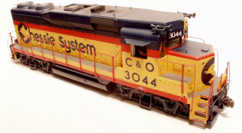
We are starting with a Proto 2000 GP30 model. The manufacturer provided the GP in Chessie livery which is the model I chose to detail. Just to point out this model is an earlier run of the GP30 by Life Like not the 2006 release.
Truck Detail
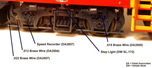
Referencing prototype photos I thought it would be easy to add some basic detail to the truck side frames.
I used brass wire bent into shape representing the various air, sand and speed recorder hoses found on prototype trucks. The sanding hoses were added by drilling a hole in the brake clamp and inserting the wire. I secured the wire with CA (super glue). Holes were also drilled into the brake cylinders to accept the air hoses.
Installing the speed recorder required that I first shave off the bolt casting on the end of the journal. Using a sharp razor I shaved off the end detail to provide a nice flat surface to drill a hole. Test fit the detail part and use CA so secure the detail in the hole you drilled. I replaced the supplied wire with brass .012 wire, this is unnecessary if you like the kit supplied wire. I think the brass wire will be more durable but this is a modeler’s choice.
A word about wire size and scale hoses. When you look at the wire thickness and translate it into “HO scale” size you will notice that the wire is over sized or too big compared to a real train. My philosophy when detailing is searching for what “looks right” but still easy to install. I am striving for the relationship of sand hoses appearing thicker than air hoses and speed recorder cables appearing to be thinner han air hoses. When we focus on the relationship of how hoses are different sizes in relation to one another we can cheat a bit and not have to fret as much about “scale” sizes. Why, because our eye tells us that the model “looks right” even though it is not “exactly right to scale size”.
Pilot and Cab Modifications
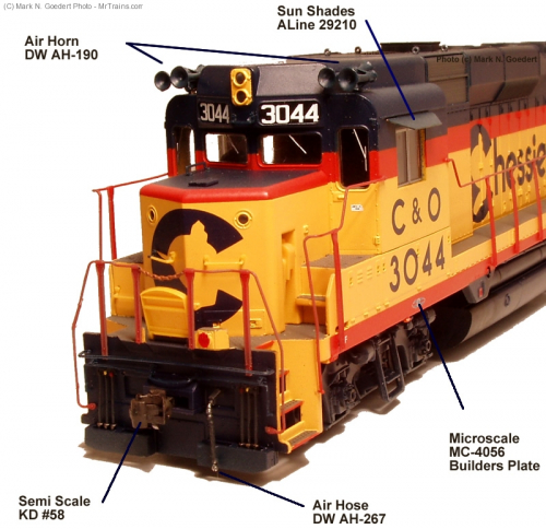
I did minor modifications to the front pilot and cab. Most notably I shaved off the front foot boards on the pilot and sanded them smooth with a small file. I added a #58 semi-scale coupler and cast metal air hose.
I added brass sunshades on both sides of the cab mounted just under the cast-on track. I installed the sunshades and painted them after they were affixed to the model. The final details are decals that I added to represent a builders plate and various warnings on the locomotive door.
Roof Detail
I removed the horn from the center of the cab roof and replaced it with two 3-Chime horns using the prototype as a guide for location. Just after construction completed I received feedback from members in the Chessie System Yahoo Group on the horn arrangement. I went back and clipped off one chime from one of the horns to convert a 3-chime horn down to a two-chime horn. The model is now a better reflection of prototype photos however I did not go back and update the photos for this web article. The image below shows the horns on the model before I made the modifications.
During construction I smashed the rear curved grab iron by accident so I replaced it with .015 brass wire, bent to fit and affixed with CA.
Fan Details
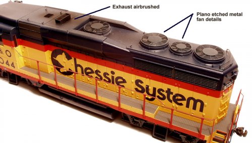
I did a bit of advanced modeling by carving out the built-in fan detail and replacing it with etched metal parts. This was the most difficult and challenging aspect of the model but well worth the results. Replacing the fan detail required a sharp hobby knife and careful placement of CA to secure the metal parts. Looking at the model, the fans are fantastic, I recommend you take your time and try this technique.
The purpose of this article is to show you a quick detail that will give impact for your time and efforts. It is the top of most models that are viewed extensively, factory details are getting better but for some models roof detailing can pay off.
Prototype Reference – I did not research this model so *disclaimer, the eight blade fan may not be “prototypical” for this unit. If anyone would like to add more information, I will be happy to credit your name and update this web page with the detail. Anyway, the eight blade fan assembly looks cool so let’s get cracking.
This is the first time I ever installed the new grill and fan arrangement. I will admit, I did not read the instructions and went right at it. I will share my mistakes along the way so you do not go down the same path.
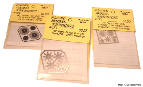
Parts – We will install pre-fit detail parts from Plano Model products. The grill detail is made from etched metal. I have found that using a new, sharp razor blade can work fine in removing the parts. I actually recommend using metal shears, they are much easier to maneuver and work with than the razor blade. A small file may also be needed to smooth out any rough cuts made on the metal parts.
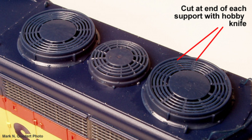
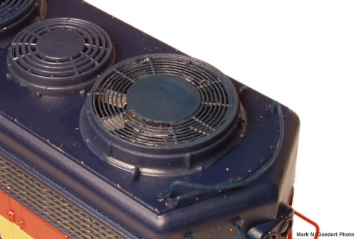
We will take a first look at the original factory fans on the model. They look pretty good but the etched metal fans are a improvement. We will use our new, sharp hobby knife to remove the existing plastic grill and replace it with the metal detail.
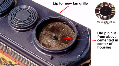
Grill Removal – Remove the existing grille by running your hobby knife along the perimeter of the fan housing. I started by cutting each support then with the grill removed I went back and cleaned up the edge. Be sure to leave the ledge around the inside of the housing, this will serve as the support for the new fan.
When you are done, the locomotive should look like this;
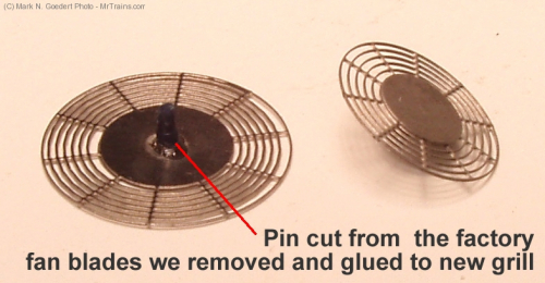
After the old grille was removed I cut the pried off the plastic fan blades. If you look at the large image you will see the remains of the pin on the old fan grill.
Parts Removal – At this time use a sharp new razor blade to remove the etched parts from the metal sprue. I highly recommend that you acquire cutting shears, they make the job a lot easier. Be careful as you work, you do not want to bend or distort the metal details. Just a warning, they bend very easily. I spent a good amount of time fixing the outer ring of the grill after I bent it accidentally.
Installing Fan Blades – You can do the installation of the fan blades two ways. In my opinion one way is easy, the other not so easy.
Easy Fan Blade Installation – The easy installation uses the existing fan button and post we removed from the model. Simply trim away the plastic grating so all you have left is the center button with the post on it. You must also pry the existing fan blades off the end of the post. It is important that you do not cut the post because we need the post in-tact to secure the new grill and fan blades to the pin.
After the fan blades are pried away insert the new grill on the post and cement it to the bottom of the button. The grill has a hole in the center that will fit on the post perfectly. After you cement the grill in place, you can place the fan blades on the post and cement them in place as well. The hole in the middle of the fan blades will also fit perfectly on the post.
If you are installing Plano etched metal blades for this project. (not required, because the existing plastic factory blades will work fine) you will have to bend each blade about 20 deg. to match the fan we removed. I used a pair of needle nose pliers to bend each blade. Once the blades are pitched properly you can glue the blades to the post and set aside to cure.
Harder Fan Blade Installation – For the next install I pre-assembled the fan and blades so I could paint them before dropping them into the model. I also used Plano metal fan blades not the factory supplied blades already in the model.
Glue the button to the top of the fan grill first. Cut the pin off the original fan and glue it to the hole on the underside of the new fan grill. Paint the grill before putting the fan blades on. I have a picture below to help illustrate.
Painting and Final Assembly – I painted the grill assembly C&O Enchantment Blue. After the paint dries put the metal fan blades on the pin and set them with a bit of adhesive. Make sure you angle the blades before you cement them to the post. This gives us blue fan grills with sliver blades inside.
Install Fan Grill – Test fit the grill on the locomotive housing. If it looks good then go ahead, remove the grill to apply adhesive. Apply glue sparingly along the ledge on the inside of the fan housing. I used a piece of brass wire to apply the glue. I laid the grill inside the housing and gently applied some pressure to the part ensuring it was all the way in and level. Be careful so you do not distort the grill by pressing too hard.
If you skipped the painting step above you can paint the grill after the adhesive has dried.
Painting – I used Polly Scale C&O Enchantment Blue to touch up the fan grill. I was careful to keep the paint away from the fan blades below. The contrast of the blue and silver blades looks really nice. I will give the housing a second coat of paint for full coverage.
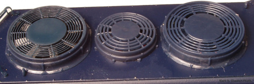
Comparison – Once the paint dries you can admire your work. Look at the image below for the final comparison of the original factory detail on the right and the new Plano parts on the left.
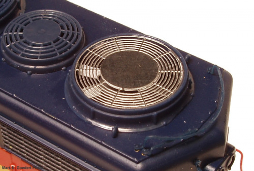
Final Product – Check out the final product below, after two evenings I completed my first set of detailed fan blades. I like the result and will apply the same effect to the other GP30 in my collection.
I did make a few mistakes along the way but none of them were insurmountable. I encourage you to give this detailing task a try. You may surprise yourself.
Weathering
The very first step was to paint all of the details we added with Polly Scale C&O Enchantment Blue. You will notice that the paint is not an exact match, not really even close, but that does not matter once we start weathering.
I picked up the following color and weathering techniques from Jim Six during one of his online clinics focusing on the NYC GP7. I thought Jim’s techniques looked great and could be applied to any diesel representing a well maintained locomotive that is in service. The GP30 is the test bed and here is what I tried.
Overall Grime – I airbrushed a mixture of; Modelflex Sand, Modelflex Grimy Black, and Modelflex Railroad Tie Brown straight down on top of the model. I only wanted to hit the roof, hood, and walkways with the spray. If you accidentally hit the sides you can use a q-tip in thinner to wipe the color away. I do not remember the exact mix of colors ( I apologize ) but I was looking for a grayish/grime look to blend in the fans and other details to the rest of the model.
Roof Exhaust – I then airbrushed a thin mix of Modelflex Engine Black around the locomotive stack. I feathered the black color towards the rear of the locomotive to simulate wind blowing the exhaust soot.
Running Gear – I mixed up a cocktail of Modelflex Sand and Modelflex Weathered Black and airbrushed a light coat over all the running gear. I wanted the color to be darker than the Overall Grime we sprayed earlier so when mixing the paint I was a little heavy on the Black. After an overall spray, I concentrated the sand mix near the wheels and journals where the sand hoses are located.
Journal Oil – I brushed on a thinned mix of Glossy Black across the journals to represent leaking oil. I varied the mix on each journal so the application did not look too uniform.
Journal Ends – I lightly dry brushed a little rust on the journal ends using Modelflex Rail Brown. I also added a little rust streak from the cast in holes on the truck side frames.
Fuel Tank – I slobbered thinned Modelflex Engine Black down the sides of the fuel tank on both sides of the locomotive. This effectively simulates fuel spillage which was very common in photos. The contrast of the grime on the running gear and spillage is very effective.
Couplers – Couplers are generally quite rusty and can are noticeable from the rest of the locomotive. I dry brushed Roof Brown and then highlighted the couplers with a dry brush of Rail Brown.
I mention the use of Floquil in the next section; Floquil is no longer available. I recommend using a readily available dull coat such as Testors or Vallejo brands and follow the paint manufacturers instructions to thin and apply the finish for best results.
Dull Coating – As a final step to protect the model I applied several coats of Floquil Flat Finish thinned 40% using Floquil thinner according to the instructions on the bottle. For the first time I used an airbrush to apply the dull finish and it looks great. I have always been an advocate of dull coating out of a spray can but applying the final finish with an airbrush has really impressed me. When applying the final finish several thin passes with the airbrush are much better than one heavy coating.
Conclusion
I was very happy with the results and I received many compliments from attendees at this year’s Trainfest in Milwaukee where the model was used during operations. I learned a lot working on this project and I was especially pleased with the fan detail and light weathering. I encourage you to expand on the article above or try some of the techniques for the first time yourself. You may be surprised at the results.
Mark N. Goedert
